27 January 2012
Isn't Your Life Worth More Than a Stupid Candy Bar Wrapper?
When you choose a nozzle, many factors go into this critical decision, or at least they should.
One major manufacturer of nozzles offers an option to prevent debris from fouling their automatic nozzle tips. The screen that they offer, is typically found at the nozzle inlet, behind the bale. In the break-apart models it is located at the inlet of the fog tip, ahead of the bale. the screen prevents larger debris that cannot be passed through the nozzle on the flush setting from fouling the nozzle. Theres a catch though....we have vandals on the prowl....
 |
| this kid has too much free time, so he thinks it would be funny to stick a candy bar wrapper in the standpipe outlet. Here, we use the gated wye attached to a flow tube, it serves the purpose just as well. |
The water flows, at 162 GPM. A nice stream forms at the nozzle, if you bleed your nozzle too quick, you'll never know whats about to happen as you step over the threshold of the door to the fire floor.
...and then, boom, catastrophic failure of the stream. This is from, a stupid candy bar wrapper....that's it.
The nozzleman is armed with a breakapart automatic nozzle, the smooth bore slug tip is 15/16" He is quick to see the potential issue and you see the result above.
Is this possibility realistic? You tell me?
Another test shows that trying the flush doesn't have any effect.
Don't die for a candy bar wrapper, buy the right equipment and know how the equipment you have works. This nozzle works very well, if you use it properly in the right applications.
Thanks to the Richmond, Virginia Fire Department for planting the seed that led to this experiment. Oddly, our nozzleman just happens to be wearing one of their hats!
Standpipes and Gated Wyes
Today, we conducted a brief experiment to determine the pressure loss in a 2 1/2" x 1 1/2" gated wye when the use of 2 1/2" hose is desired. A 20' section of 2 1/2" hose was attached to the flow tube on the fire hydrant. We used adapters in place of a bushing on the outlet of the wye with the following results;
With gated wye. 1 1/8" tip, 250 GPM. The flow was verified with a flow meter and handheld pitot gauge. Pressure at hydrant was 83 PSI. Tip pressure 50 PSI. Pressure loss was 33 PSI
Without gated wye. Same tip, same flow. Pressure at hydrant was between 48 and 50 PSI with corresponding tip pressure readings, meaning the pressure loss was negligible without the wye.
Assume a loss of 25 to 30 PSI through the valve with a setup like this. As you can see, the old 10 PSI loss is a big underestimate here.
29 December 2011
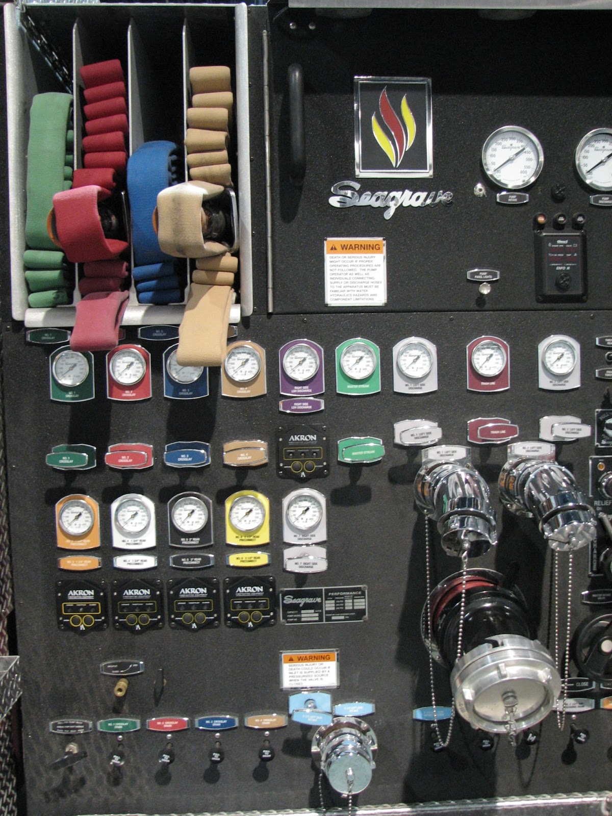
Attack Lines. Crosslay or Hosebed?
A question was posed by one of our readers today regarding the differences in having attack lines located as crosslays versus being in the rear hosebed. The location of attack lines varies from department to department, and also from apparatus manufacturer to manufacturer. Lets look at some of the considerations that go into this critical decision.
It seems pretty common to find attack lines located above the pump house in the "crosslay" configuration. Another common transverse configuration is the "speedlay", which is found located in the walkway of top mount pumpers or through the body of some styles of rigs. These configurations offer some different options, from width, to piping configuration and in some cases, the hose may even be stored in plastic bins that slide into the chutes. Available options for these transverse hose loads include piping located inside the hose slot (with the standard swivel connection) as well as piping located on the pump panels just below the hosebed (LA Style). Piping in the hose slots may be located so that it is under the hose load, or in some cases (speedlays) the swivel connections may be located above the hose loads.
Crosslay and speedlay hose locations and configurations can be slaves to other pump and apparatus features. When you specify certain pump and valve features, the pump house must be a certain size, which may cause issues with height and capacity of crosslay slots. Most manufacturers build standard hose slots for 200 foot crosslays, because that seems to be the typical amount of hose carried. At specification meetings, make sure to make your desired hose slot height and capacity known. Additionally, the type of hose load used may factor in. If using a minuteman, for example, you may want a single stack slot or a dual stack slot. Either way, you need to know and state this when you work through the specification process.
Some advantages of crosslay/transverse hose loads?
Don't forget the pigtail!. If you want the flexibility of being able to break and extend crosslay lines or disconnect to repack, a pigtail section of hose from the swivel to the ground is a great idea. The length will be determined by the height of your hosebed. We use 10' lengths. Its a good idea to use a bright, different color hose to also visually indicate the attack line is fully deployed.
Now, onto rear hosebeds. This option is somewhat "old school", as its where hose was usually stored on the first motorized fire apparatus. Rear hosebed attack line storage went out of favor with the dawn of the crosslay (Mattydale to some). Some departments never changed the way they stored and deployed their hose, because...well...it worked. Working off the rear bed usually adds more flexibility when your rigs are able to have a hose bed height that's within reachable distance from the ground. On rigs with large water tanks and rescue bodies, hose beds are forced to be raised to accommodate those body features, and storage of attack lines may be more favorable as crosslays or even up in the bumper.
Rear hosebed attack lines are typically loaded into slots in the hosebed. There are a few factors to consider with rear hosebeds.
Does the water tank have anything to do with it? Sure it does. An "L" tank will lower the hosebed floor. "L" tanks are available in both rectangular and "T" styles. The "L" shape is determined by the side view. The "T" by looking at the front or back. Our rig has an "L" shaped "T" tank to allow for the standard pumper body configuration with a low hosebed.
Specification language used when we built our rig for the hosebed reads as follows:
Some final points to ponder, regarding the hose and nozzles. Hose varies in dimension by brand and model. The difference in how hose is manufacturered means you may only fit 150 feet of brand A hose in your slot and 250 feet of brand B. Get your hands on samples, see how it packs, deploys and performs. Ask departments that are using hose alot what they have. Nozzles are another factor. Your hose bed slots, particularly for crosslays, need to account for the nozzles you choose. Remember, certain hose loads like a minuteman will not allow the nozzle to pass the opposite direction than how it is loaded. Pistol grips may also create issues in narrow hose slots. Make sure there is space for them. There is nothing worse than having your new rig show up and finding out you can't pack your hose into the attack line slots like you wanted because of a manufacturing issue. In the end, it is most likely the failure to plan that results in such an occurrence.
We didn't talk about it here, but remember, front bumpers aren't just for trash lines. Preconnects of up to 200 feet can easily be stored in front bumper wells. On many engines, otherwise unused bumper space can make way for additional hose wells, offering two attack lines up front, down low and still leaving space for a front intake and soft sleeve.
Your goal, with attack lines, should be to have a setup that is designed with the following key points in mind;
Stay safe, think critically and train hard.
M.G.
It seems pretty common to find attack lines located above the pump house in the "crosslay" configuration. Another common transverse configuration is the "speedlay", which is found located in the walkway of top mount pumpers or through the body of some styles of rigs. These configurations offer some different options, from width, to piping configuration and in some cases, the hose may even be stored in plastic bins that slide into the chutes. Available options for these transverse hose loads include piping located inside the hose slot (with the standard swivel connection) as well as piping located on the pump panels just below the hosebed (LA Style). Piping in the hose slots may be located so that it is under the hose load, or in some cases (speedlays) the swivel connections may be located above the hose loads.
 |
| Standard crosslays with pipe connections at the bottom of the load. This rig has lower than typical height crosslays, which would make it much easier to pull the line. NFPA requirements for hosebed covers, however, slow down hose depoyment. |
 |
| These "Speedlays" have plastic bins, so the hose can be loaded outside the rig. As such, the pipe connections are above the hose, which may cause some difficulty with certain types of hose loads. |
 |
| With single stack, low crosslays, 4 slots here allow two lines to run off each side. Pipe connections in the bottom of the slots require the entire line to be preconnected. If you prefer different length lines, this is a perfect setup to have one of each length off each side. |
 |
| LA Style. This design uses a single discharge under the transverse beds on each side. The connection is on the panel, not in the slot. This allows the transverse beds to be used more like traditional hose beds. Some departments use an appliance on this discharge, some have several discharges located on each side. |
Some advantages of crosslay/transverse hose loads?
- They are quick to deploy
- They are pre-engineered and standard features on rigs
- They are a better place to put attack lines on rigs that have high hosebeds or aerial/quints with limited hosebeds.
- When you are using pipe connections on the panels, versus in the hose slot, they offer similar flexibility to rear hosebeds.
- The length of a crosslay bed makes the hose load the right size for shouldering, as it is typically no more than 8' long.
- Hose capacity may be limited due to apparatus design
- Height of crosslays may be extreme due to pump house and other apparatus design issues
- Hose will often be in the operators working area (many times near their head) when in service
- When pipe connections are in the bed, the entire load must be preconnected, meaning you cannot store dead load hose under the preconnect to extend the line.
- Piping runs may necessitate the use of several elbows, resulting in high friction loss
- Many times, crosslays are so high, grabbing and deploying them is almost dangerous.
Don't forget the pigtail!. If you want the flexibility of being able to break and extend crosslay lines or disconnect to repack, a pigtail section of hose from the swivel to the ground is a great idea. The length will be determined by the height of your hosebed. We use 10' lengths. Its a good idea to use a bright, different color hose to also visually indicate the attack line is fully deployed.
 |
| Preconnect pigtail, with nozzle and gauge attached during a flow test to determine piping friction loss. |
 |
| You can see the bight blue pigtail in the background as well in the drivers hands. This allowed a 200' line to be extended with a donut roll in about 40 seconds. Had the connection been in the bed it would have been much harder. |
Now, onto rear hosebeds. This option is somewhat "old school", as its where hose was usually stored on the first motorized fire apparatus. Rear hosebed attack line storage went out of favor with the dawn of the crosslay (Mattydale to some). Some departments never changed the way they stored and deployed their hose, because...well...it worked. Working off the rear bed usually adds more flexibility when your rigs are able to have a hose bed height that's within reachable distance from the ground. On rigs with large water tanks and rescue bodies, hose beds are forced to be raised to accommodate those body features, and storage of attack lines may be more favorable as crosslays or even up in the bumper.
 |
| A Firefighter, standing at 5'7" easily reaches this rear attack line, with a 61" Hosebed floor. The 400' line is ideal for apartments and long setbacks. The hose connection is at the tailboard, allowing this line to be broken at any length and utilized. |
- How high is the hosebed? Does the hosebed floor height lend itself to ease of attack line loading and deployment? Some rigs must have a high hosebed to accommodate tanks, ladders or compartments. This may make them unfavorable for attack lines.
- How deep is the hosebed? A shallow hosebed will require hose to be stacked higher, and may make reaching the top of the hose load difficult. A long/deep bed will cause the hose to be too long to shoulder load, and result in it dragging on the ground. Hose beds for attack lines should be no greater than 8 feet deep. This gives you 4 feet of hose in front and behind you, if you shoulder the load.
 |
| Discharge at the tailboard. This configuration also allows additional dead load hose to be kept under the preconnect. This slot has 400' of 1 3/4", with 250' preconnected. |
 |
| Make sure the dividers for the rear hose beds are the proper size. Dividers that are too tall will make repacking the hose nearly impossible. These dividers are sized just right. |
 |
| This rig has a nice large tailboard, with attack lines off the rear. It is well suited for the tasks of an engine company. |
 |
| This squad companty has a rescue body design, which does not make the rear hosebed favorable for attack lines. They overcame this with four very low "LA" style crosslays |
Does the water tank have anything to do with it? Sure it does. An "L" tank will lower the hosebed floor. "L" tanks are available in both rectangular and "T" styles. The "L" shape is determined by the side view. The "T" by looking at the front or back. Our rig has an "L" shaped "T" tank to allow for the standard pumper body configuration with a low hosebed.
Specification language used when we built our rig for the hosebed reads as follows:
6.18 HOSE BED
The hose bed floor shall be a no more than 60” from ground level. It shall be no deeper than 8 feet. This shall be accomplished utilizing an L shaped type water tank.
The hose bed shall be provided with aluminum slatted flooring radiused at the edges to prevent hose damage from sharp edges. Each hose bed floor section shall be removable for easy access to the water tank.
 |
| The tank in our rig is "T" shaped, looking at it from the rear, but it is an 'L" tank to facilitate a lower hosebed. |
We didn't talk about it here, but remember, front bumpers aren't just for trash lines. Preconnects of up to 200 feet can easily be stored in front bumper wells. On many engines, otherwise unused bumper space can make way for additional hose wells, offering two attack lines up front, down low and still leaving space for a front intake and soft sleeve.
Your goal, with attack lines, should be to have a setup that is designed with the following key points in mind;
- Safety. can your firefighters reach and deploy the lines without climbing up on the rig? If they have to climb, is the stepping surface such that they can climb and deploy the hose without assistance and maintain balance?
- Ease. How easy can you pack and deploy the lines?
- Flexibility and Efficiency. How much hose do you have? how is it packed? Is it good for your first due district? What about your second due districts? Is it adaptable? Can you extend and stretch shorter than the preconnected length?
Stay safe, think critically and train hard.
M.G.
23 December 2011
Adapters and Appliances. Your Puzzle Pieces to Success
Toady's post promises to be a winner for those of you who, like me, enjoy articles with pictures.
Adapters and appliances are some of the most critical pieces of equipment carried by engine companies. As a driver/operator, it is your duty to know what each adapter is and the multitude of possible uses. Many times, adapters are mounted, in a nice organized fashion and used so rarely, that they end up being not much more than decorations in the compartments. With the dynamic nature of a fireground, having a driver who has quick thinking skills and and possesses the ability to overcome challenges is a must. When that driver knows the equipment on the rig, it makes everything come together in critical times of need.
The question of how many and which type of adapters is really one that needs to be discussed amongst each department. In the following illustrations, some typical adapters and appliances will be shown, along with their uses. The limit to what you can do with appliances and adapters is really endless, as long as you stay within the safe working limits of the equipment.
Having the right adapters and appliances is the starting point. Organization and storage comes next. Are your adapters and appliances stored in a way that they are easy to locate, identify and remove from the rig? With a multitude of different brackets on the market, try out the options at trade shows or apparatus vendors shops, so that you can see what is best suited for your needs and preferences. Most importantly, are your most commonly used adapters attached to the pump connections and hoses you use most. It makes alot of sense to have the adapters already in place on the rig, rather than having to always pull them from a compartment each time they are needed.
 |
| These two rigs have a variety of different adapters and appliances. Additional adapters are attached to connections around the rigs. In the photo above, adapters are mounted on "PAC" mounting boards, allowing for flexibility in mounting arrangements. |
 |
| This "Respond Ready" brand tool chest is being used for adapters and appliances |
 |
| This rig uses "Zico" stud type mounting brackets on a pull out tray. |
 |
| Adapters attached at point of use accomplishes two key things. First, it allows the driver to make connections with various common hose connections that may be used within the department or with second and third due companies and secondly, it allows your compartment to have space for additional, or less frequently used ones. |
 |
| This rig has some adapters already attached to its connections. The Hale 8FG 2500 GPM pump has two main inlets and two LDH discharges on the officers side. The forward inlet has a cap, for use when drafting, to make it more obvious that this is the most direct inlet to the pump. The inlet next to it has a storz adapter, because it has a slight bend to direct it into the custom built intake manifold, making is a little less efficient for drafting and better suited for use with a pressurized supply. The forward LDH discharge has a 5" to 4" storz reducer, indicating it is the preferred primary discharge for LDH, as it has the shortest run of pipe. |
 |
| Doubles. Double male and female adapters come in handy for a variety of uses. They are often used when converting a bed of 2 1/2" or 3" from attack to supply or supply to attack, offering greater flexibility. 1 1/2" Doubles, seen here are not often used, but good to keep handy. |
 |
| The 1 1/2" double female is a great adapter to use when backflushing the pump. |
 |
| 2 1/2" Double female and double male. |
 |
| This gated wye is now a Siamese, by using 2 1/2" double male and female adapters. |
 |
| When FDC connections are frozen and will not swivel, a double male and double female will make a quick fix. |
 |
| The same gated wye is now adapted for use as a siamese to 4" Storz |
 |
| A 2 1/2" double female and double male extends the discharge on this ball valve so that the handle can open all the way with using a 4 or 5" storz adapter. |
 |
| Reducers. These are very common. Many of them are chrome plated, because they are often found attached to the pump discharges. Reducers are an excellent adapter to allow use of multiple handlines on wye and water thief appliances. |
 |
| This double female adapter has a rigid, rocker lug 6" base with a swivel 4 1/2" connection attached. This half rigid, half swivel adapter is best suited when used when the rigid connection is already attached so the hose can be connected using the swivel. Such examples would include for connecting suction hose of a different diameter to the pump inlet or when using dry hydrants. |
 |
| This double female has swivels on both sides. Like other adapters, they come in various thread and diameter options. These are better suited when you want to make connections easier, as both sides will swivel, even if one side is already connected. Typical applications are drafting connections when seen in the above configuration. The long handles allow easier connections without the necessity for a wrench. |
 |
| This double female is a similar configuration as above, however it has different diameter threads on each side (4 1/2" x 6") |
 |
| Storz adapters are critical if you run with companies that use different diameter Storz connections. Its best to carry at least two of them, as you would be in a tricky situation if you came upon a hydrant valve that is 4" and your rig carried 5". |
 |
| This gated wye is 2 1/2" inlet by 2 1/2" outlets. A 2 1/2" male x 4" Storz adapter makes it useful with large diameter hose, although the waterway is slightly smaller than if the wye had a Storz adapter permanently affixed to it. It just shows you an additional option. |
 |
| Keeping reducers on gated wyes increases their versatility and saves time looking for adapters when in time of critical need. |
 |
| A 1 1/2" inlet x 1 1/2" outlet hated wye is good for use on front bumper or pump discharges where multiple lines may be used. This one has a 1" reducer for use with forestry hose. |
 |
| Storz x female adapters. On the left is a rigid female, on the right is a swivel female. |
 |
| The rigid female x strorz adapter is a good choice for use on discharges |
 |
| The rigid female x storz adapter on the auxiliary inlet. |
 |
| The rigid female x storz adapter is NOT a good choice on this inlet, because it must be removed and attached to the hose if using 2 1/2" threaded hose. |
 | ||
| A 5" Storz discharge has been reduced to 2 1/2" using several adapters. The base adapter is 5" Storz x 4" Storz, followed by 4" Storz to 2 1/2" rigid female, and finished with a 2 1/2" double male. This illustration shows how you can make it work, but it would be better to purchase more suitable adapters if you typically use this discharge in such a configuration.
|

 |
| If you have companies using different diameter LDH, its best to spec the base thread with 5" and then reduce it to 4". This rig carries 4" hose, but all pump connections have 5" Storz base thread to make the waterways larger. |
 |
| Auxiliary suctions, while not nearly as efficient as the main pump inlets, should be spec'd with larger piping than the standard 2 1/2". Here 3" base thread (pipe and valve) is adapted to a 3" female rigid x 4" storz adapter. A 4: Storz x 2 1/2" female swivel is then fitted with a 2 1/2" plug. This allows the auxiliary suction to receive 4" hose, providing additional water flow when needed. |
 |
| This assortment of adapters will allow 4" storz hose to connect to the 3" auxiliary inlet, but because there is a 2 1/2" threaded adapter behind the storz adapter, it reduces the waterway opening, creating a restriction. Its always best to use the large adapter with storz fitting at the base and reduce it to the smaller, 2 1/2" thread. |
 |
| This auxiliary suction inlet has 3" piping and valve. A 3" male x 2 1/2" female swivel adapter is fitted to allow the connection of 2 1/2" couplings, while providing a more efficient waterway, due to the larger pipe and valve. |
  |
| Storz x Male rigid thread adapters can be used for many things. This one is intended for use on the inlet of a Humat valve to convert it to an inline relay valve. It can also be used as pictured below. |
 |
| Using the 4 1/2" threaded x storz adapter on a gate valve will allow your front intake sleeve to be able to connect when using hydrants with only 2 1/2" discharges. |
 |
| Even if your company uses 4" hose, if there are companies in your adjacent districts that use 5", it makes more sense to furnish your large diameter intakes and discharges with the 5" base connection and reduce it to 4". This will typically allow for a larger waterway at the base of the connection, for greater efficiency. |
 |
| This Tanker Company keeps storz adapters preconnected to their fill lines, to save set-up time. |
 |
| This specialty adapter converts an atypical thread (base) to 4 1/2" NST on older hydrants in one NJ community. |
 |
| The long handle, swivel threaded x storz adapter is the best choice when you need an adapter that is left connected to a hose. Its swivel connection allows it to be attached to the hydrant or other connection without having to remove it from the hose. |
 |
| The rigid female x storz adapter is best used when already attached to the pump intake or discharge. When using threaded by storz adapters on hose, its more ideal to use swivel style, which allow the hose to be connected without having to remove the adapter. |
Hopefully this article has offered some insight regarding the value and purpose of the multitude of adapters carried on our rigs. This is only a sampling of the different options available. The best practice is to go through your rig and pull them out and figure out where they fit and what you can do with them.
As a quick recap, for guidance when ordering, here are the terms you need to remember when specifying adapters.
- Rigid. The thread is attached in a manner it will not swivel or rotate. All male threads are rigid, but you have the option to specify female thread as rigid. Use rigid female thread when adapters will normally be attached to pump or hydrant connections or where the adapter will never have to rotate to connect a hose to it.
- Swivel. The female swivel thread is necessary if an adapter is going to be threaded onto a hard connection (or another hose). The most common swivel adapter is the hydrant adapter, used on LDH. Once tightened, swivel adapters will be tight, and will not swivel anymore, unless extreme force is applied.
- Full Time Swivel. These types of swivel adapters will maintain full rotation capability when connected. They are often found on Humat valves, and LDH intakes, to prevent the hose from becoming knotted as it charges and twists. These are tricky, because you may need two wrenches to make connections, as the fitting doesn't always offer enough resistance to allow for turning and locking a coupling.
- Rocker lug. You have the option, on the adapters you specify, to choose the lug style. Rocker lugs are the standard lug found on most threaded fire hose. They work well on couplings up to about 2 1/2". Once you get beyond that size, long handles offer easier connecting and provide good leverage for making them tight.
- Long handle. Long handle lugs are the preferred style for suction hose connections/adapters, hydrant adapters and pump intake adapters. They will take up a little more space though.
- Folding handle. Some LDH adapters and fittings have folding handles, for greater leverage and ease of connection, while allowing them to fold away for lower profile when not being used.
Feel free to contact us if you need any guidance with adapters and appliances. Stay safe.
Subscribe to:
Posts (Atom)