It seems pretty common to find attack lines located above the pump house in the "crosslay" configuration. Another common transverse configuration is the "speedlay", which is found located in the walkway of top mount pumpers or through the body of some styles of rigs. These configurations offer some different options, from width, to piping configuration and in some cases, the hose may even be stored in plastic bins that slide into the chutes. Available options for these transverse hose loads include piping located inside the hose slot (with the standard swivel connection) as well as piping located on the pump panels just below the hosebed (LA Style). Piping in the hose slots may be located so that it is under the hose load, or in some cases (speedlays) the swivel connections may be located above the hose loads.
 |
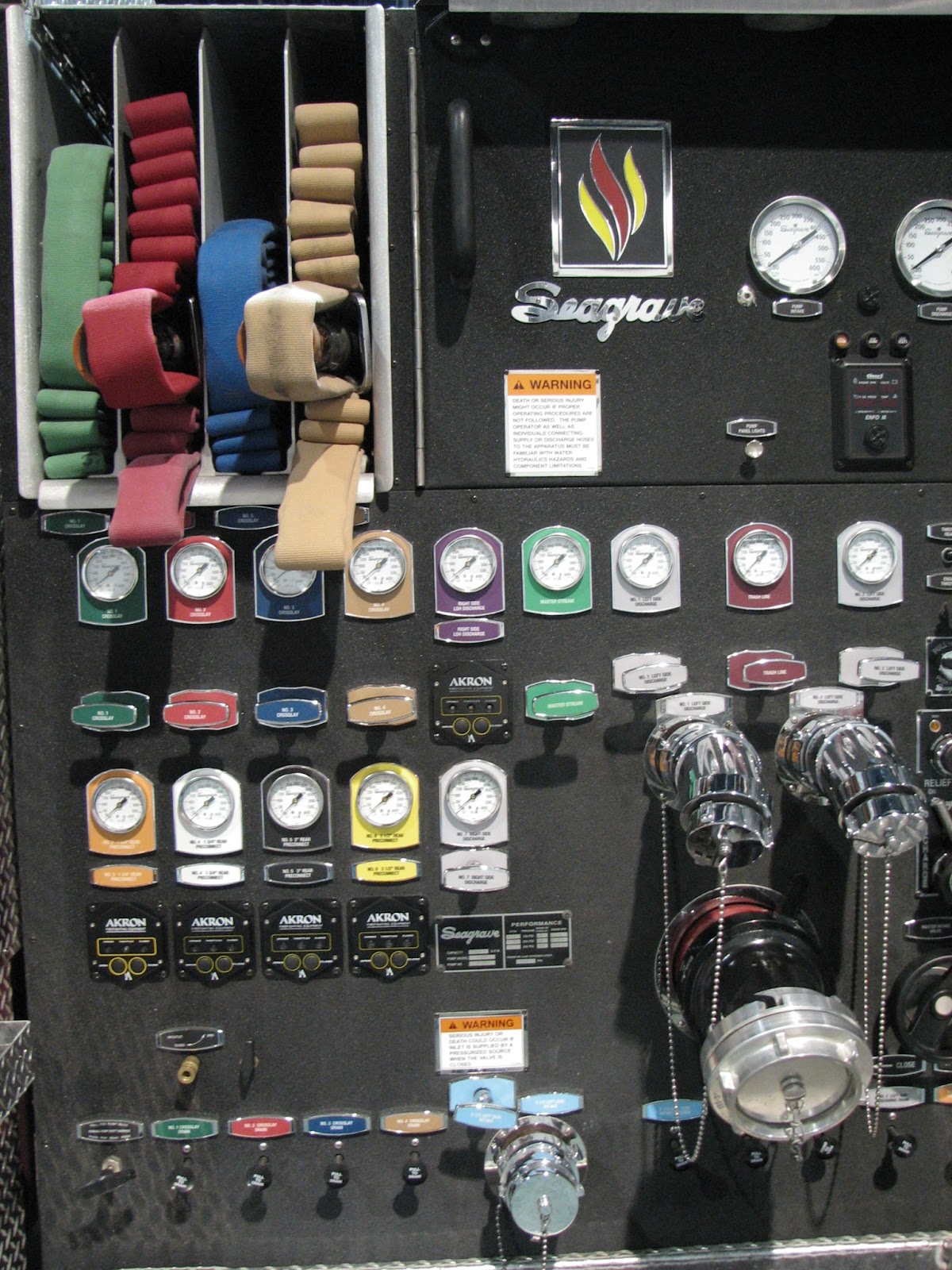
| Standard crosslays with pipe connections at the bottom of the load. This rig has lower than typical height crosslays, which would make it much easier to pull the line. NFPA requirements for hosebed covers, however, slow down hose depoyment. |
 |
| These "Speedlays" have plastic bins, so the hose can be loaded outside the rig. As such, the pipe connections are above the hose, which may cause some difficulty with certain types of hose loads. |
 |
| With single stack, low crosslays, 4 slots here allow two lines to run off each side. Pipe connections in the bottom of the slots require the entire line to be preconnected. If you prefer different length lines, this is a perfect setup to have one of each length off each side. |
 |
| LA Style. This design uses a single discharge under the transverse beds on each side. The connection is on the panel, not in the slot. This allows the transverse beds to be used more like traditional hose beds. Some departments use an appliance on this discharge, some have several discharges located on each side. |
Some advantages of crosslay/transverse hose loads?
- They are quick to deploy
- They are pre-engineered and standard features on rigs
- They are a better place to put attack lines on rigs that have high hosebeds or aerial/quints with limited hosebeds.
- When you are using pipe connections on the panels, versus in the hose slot, they offer similar flexibility to rear hosebeds.
- The length of a crosslay bed makes the hose load the right size for shouldering, as it is typically no more than 8' long.
- Hose capacity may be limited due to apparatus design
- Height of crosslays may be extreme due to pump house and other apparatus design issues
- Hose will often be in the operators working area (many times near their head) when in service
- When pipe connections are in the bed, the entire load must be preconnected, meaning you cannot store dead load hose under the preconnect to extend the line.
- Piping runs may necessitate the use of several elbows, resulting in high friction loss
- Many times, crosslays are so high, grabbing and deploying them is almost dangerous.
Don't forget the pigtail!. If you want the flexibility of being able to break and extend crosslay lines or disconnect to repack, a pigtail section of hose from the swivel to the ground is a great idea. The length will be determined by the height of your hosebed. We use 10' lengths. Its a good idea to use a bright, different color hose to also visually indicate the attack line is fully deployed.
 |
| Preconnect pigtail, with nozzle and gauge attached during a flow test to determine piping friction loss. |
 |
| You can see the bight blue pigtail in the background as well in the drivers hands. This allowed a 200' line to be extended with a donut roll in about 40 seconds. Had the connection been in the bed it would have been much harder. |
Now, onto rear hosebeds. This option is somewhat "old school", as its where hose was usually stored on the first motorized fire apparatus. Rear hosebed attack line storage went out of favor with the dawn of the crosslay (Mattydale to some). Some departments never changed the way they stored and deployed their hose, because...well...it worked. Working off the rear bed usually adds more flexibility when your rigs are able to have a hose bed height that's within reachable distance from the ground. On rigs with large water tanks and rescue bodies, hose beds are forced to be raised to accommodate those body features, and storage of attack lines may be more favorable as crosslays or even up in the bumper.
 |
| A Firefighter, standing at 5'7" easily reaches this rear attack line, with a 61" Hosebed floor. The 400' line is ideal for apartments and long setbacks. The hose connection is at the tailboard, allowing this line to be broken at any length and utilized. |
- How high is the hosebed? Does the hosebed floor height lend itself to ease of attack line loading and deployment? Some rigs must have a high hosebed to accommodate tanks, ladders or compartments. This may make them unfavorable for attack lines.
- How deep is the hosebed? A shallow hosebed will require hose to be stacked higher, and may make reaching the top of the hose load difficult. A long/deep bed will cause the hose to be too long to shoulder load, and result in it dragging on the ground. Hose beds for attack lines should be no greater than 8 feet deep. This gives you 4 feet of hose in front and behind you, if you shoulder the load.
 |
| Discharge at the tailboard. This configuration also allows additional dead load hose to be kept under the preconnect. This slot has 400' of 1 3/4", with 250' preconnected. |
 |
| Make sure the dividers for the rear hose beds are the proper size. Dividers that are too tall will make repacking the hose nearly impossible. These dividers are sized just right. |
 |
| This rig has a nice large tailboard, with attack lines off the rear. It is well suited for the tasks of an engine company. |
 |
| This squad companty has a rescue body design, which does not make the rear hosebed favorable for attack lines. They overcame this with four very low "LA" style crosslays |
Does the water tank have anything to do with it? Sure it does. An "L" tank will lower the hosebed floor. "L" tanks are available in both rectangular and "T" styles. The "L" shape is determined by the side view. The "T" by looking at the front or back. Our rig has an "L" shaped "T" tank to allow for the standard pumper body configuration with a low hosebed.
Specification language used when we built our rig for the hosebed reads as follows:
6.18 HOSE BED
The hose bed floor shall be a no more than 60” from ground level. It shall be no deeper than 8 feet. This shall be accomplished utilizing an L shaped type water tank.
The hose bed shall be provided with aluminum slatted flooring radiused at the edges to prevent hose damage from sharp edges. Each hose bed floor section shall be removable for easy access to the water tank.
 |
| The tank in our rig is "T" shaped, looking at it from the rear, but it is an 'L" tank to facilitate a lower hosebed. |
We didn't talk about it here, but remember, front bumpers aren't just for trash lines. Preconnects of up to 200 feet can easily be stored in front bumper wells. On many engines, otherwise unused bumper space can make way for additional hose wells, offering two attack lines up front, down low and still leaving space for a front intake and soft sleeve.
Your goal, with attack lines, should be to have a setup that is designed with the following key points in mind;
- Safety. can your firefighters reach and deploy the lines without climbing up on the rig? If they have to climb, is the stepping surface such that they can climb and deploy the hose without assistance and maintain balance?
- Ease. How easy can you pack and deploy the lines?
- Flexibility and Efficiency. How much hose do you have? how is it packed? Is it good for your first due district? What about your second due districts? Is it adaptable? Can you extend and stretch shorter than the preconnected length?
Stay safe, think critically and train hard.
M.G.
No comments:
Post a Comment